Once the tools is started, you are asked to define the area of interest:
Specify first corner point or [Select/Inside/Mosaic]:
Specified area is displayed using red dashed lines on the screen. Based on your preferences and available reference objects, TopoPlanner provides following ways of defining area of interest:
Pressing ESC at any time cancels the command execution.
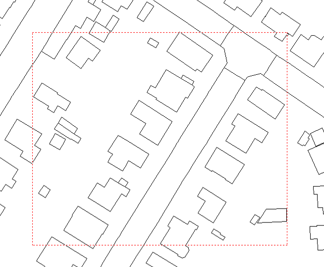
This is default area selection mode. You are asked to pick first and second corner points of a rectangle representing area of interest:
|
|
Selected area |
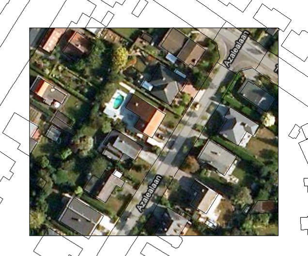
Resulting image |
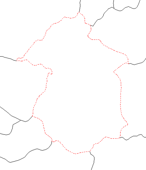
By entering Select keyword you are asked to select a single closed contour object - either polyline or polygon. Outer boundary of selected polygon represents the clipping boundary of resulting raster image:
|
|
Selected boundary |
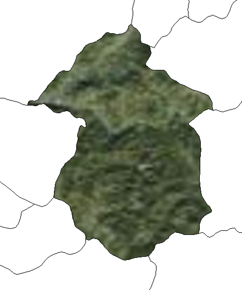
Resulting image |
Picking Inside a Closed Contour
By entering Inside keyword you are asked to pick a point inside closed contour. This option is used if there's no single object constituting region of interest. Outer boundary of resulting polygon, if any, represents the clipping boundary of resulting raster image.
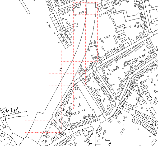
By entering Mosaic keyword you are asked to firstly select one or more objects constituting either sites (polygons, regions) or bands along linear corridors (roads, highways, railroads, canals, rivers etc.):
Select objects or [LAYer/BLock/Object/CLass/SPatial/ALL/Previous/Undo]:
Default selection mode enables you freely select one or more objects in the drawing, but you can also pick different selection methods. Following table describes each of the above selection keywords, in addition to standard AutoCAD selection methods:
Keyword |
Description |
LAYer |
Selects all objects on specified layer. You can specify layer name either by picking an object residing on it, or typing in layer name using list of existing layers. |
BLock |
Selects all specified block references in the drawing. You can specify block name either by picking a block entity, or typing in block name using list of existing blocks. |
Object |
Selects all entities of specified type (e.g. Line, Polyline, Point, etc.). You can specify object type either by picking desired object in a drawing, or typing in object name using list of existing entity types. |
CLass |
Selects all objects of specified feature class. You can specify feature class name either by picking an object representing one, or typing in feature class name using list of existing classes. |
SPatial |
Selects all objects in a drawing satisfying specified spatial constraint. |
ALL |
Selects all objects in active drawing. Please bear in mind that objects on frozen layers are ignored and therefore not selected, whereas objects on layers that are off are selected. |
Previous |
Reuses previous selection set. |
Undo |
Undoes last selection addition (if any). |
Window |
Select by window. Using window, objects must lie completely within the window boundary to be selected. |
Crossing |
Select by crossing window. Contrast to select by window, objects either within the window or crossed by the boundary are selected. |
Last |
Selects the last entity drawn from the objects currently visible (if any). |
Fence |
Select by fence. Fence selects all objects crossing specified polyline. |
WPolygon |
Select by window polygon. Objects must lie completely within the specified polygonal boundary to be selected. |
CPolygon |
Select by crossing window polygon. Objects either within the specified polygonal boundary or crossed by the boundary are selected. |
Remove |
Removes specified objects from the current selection set. |
After you select objects of interest, wizard asks you specify buffer distance:
Specify object(s) buffer <5.0000>:
Provided distance (expressed in current linear units ) represents a polygonal buffer distance constructed around selected objects. It ensures that all objects from selection set get properly covered by the resulting raster imagery. Please note that larger buffer values also may result in raster tiles further away from selected objects (e.g. tiles that don't cover any of the objects, which you can manually delete later). Next, wizard asks you to:
Specify image width <50.0000>:
Specify image height <50.0000>:
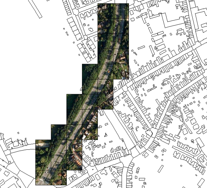
Provided image width and height (expressed in current linear units) represent size of a single raster image tile rectangle in the drawing. Please note that model space, not paper space, measures should be used. Resulting tile set may look like following:
|
|
Selected area/tiles |
Resulting image tiles |